Home
› Wiring Diagram Wire Engine Schematicze / TheSamba.com :: Karmann Ghia Wiring Diagrams / Type of wiring diagram wiring diagram vs schematic diagram how to read a wiring diagram:
Wiring Diagram Wire Engine Schematicze / TheSamba.com :: Karmann Ghia Wiring Diagrams / Type of wiring diagram wiring diagram vs schematic diagram how to read a wiring diagram:
Type of wiring diagram wiring diagram vs schematic diagram how to read a wiring diagram: The following diagrams may differ slightly depending on vehicle year, or model (california or federal). Better for multiple fuel pumps. Only the key on the dash would turn off the motor. Symbols that represent the components in the circuit, and lines that represent the.
Bayliner Engine Wiring Diagram - Wiring Forums from i2.wp.com The last circuit was added on thursday, november 28, 2019.please note some adblockers will suppress the schematics as well as the advertisement so please disable if the schematic list is empty. Volvo i have 6 koeran euro 6 type dump trucks 460hp.500hp.540fmx i need electrical wiring diagram and full error code due to engine error. However, basic schematics of our alternator systems wired to a generic piece of equipment are available in our Only the key on the dash would turn off the motor. A wiring diagram is a simplified standard pictorial representation of an electrical circuit. 4 wire reversible psc motor with a triple pole double throw switch. Confirm that the diagram shown corresponds to your vehicle by referencing the factory repair manual. Electrical schematic & wiring diagrams.
Ac80, ac90, ac100 single phase motors.
Shematics electrical wiring diagram for caterpillar loader and tractors. Unlike a schematic diagram, which can be thought of as a conceptual drawing, the wiring diagram is designed for end users and installers who focus on making connections and troubleshooting components. Volvo truck wiring diagrams pdf; A block diagram is used as an aid for troubleshooting complex electrical and electronic systems. 1 831 168 просмотров 1,8 млн просмотров. Need a wiring diagram for a onan gen set for 14 hp briggs and stratton wiring diagram. A wiring diagram is a simple visual representation of the physical connections and physical layout of an electrical system or circuit. Wouldn't it be nice if you could get the full schematics, interior photos, and other technical detail before you even pick up a screwdriver? This is a decent step by step and doesnt require the engine to be removed t. Ac80, ac90, ac100 single phase motors. Type of wiring diagram wiring diagram vs schematic diagram how to read a wiring diagram: Wiring diagrams are often used for troubleshooting electrical malfunctions. Suits all smc ecus ).
Snapper NZMJ25613KH (7800025) 61" 25 HP Kohler Mid Mount Z-Rider Series 3 Parts Diagram for ... from az417944.vo.msecnd.net The last circuit was added on thursday, november 28, 2019.please note some adblockers will suppress the schematics as well as the advertisement so please disable if the schematic list is empty. It reveals the parts of the circuit as streamlined forms, and the power and also signal links between the devices. Blue wires schema is for starter wiring, pink for igniter wiring, red for interior power source, and green for 2 sensor wiring. However, basic schematics of our alternator systems wired to a generic piece of equipment are available in our Wiring diagrams should identify all equipment parts. 1 831 168 просмотров 1,8 млн просмотров. A wiring diagram is a simple visual representation of the physical connections and physical layout of an electrical system or circuit. Better for multiple fuel pumps.
Wiring diagrams for autronic products, including engine management, ignitions.
Wiring diagrams should identify all equipment parts. As already written earlier regarding the lv switchboard, wiring diagrams are used to show the control and signalization principle of operation inside the switchboard. However, basic schematics of our alternator systems wired to a generic piece of equipment are available in our Wiring diagrams for autronic products, including engine management, ignitions. (engine room main wire) wire color : 1 831 168 просмотров 1,8 млн просмотров. A wiring diagram is a type of schematic that uses abstract pictorial symbols to show all the interconnections of components in a system. Locate the engine control unit (ecu) using the. Better for multiple fuel pumps. Cd urea dosing system 1/2. There are 2777 circuit schematics available. Variety of kohler engine wiring schematic. Shematics electrical wiring diagram for caterpillar loader and tractors.
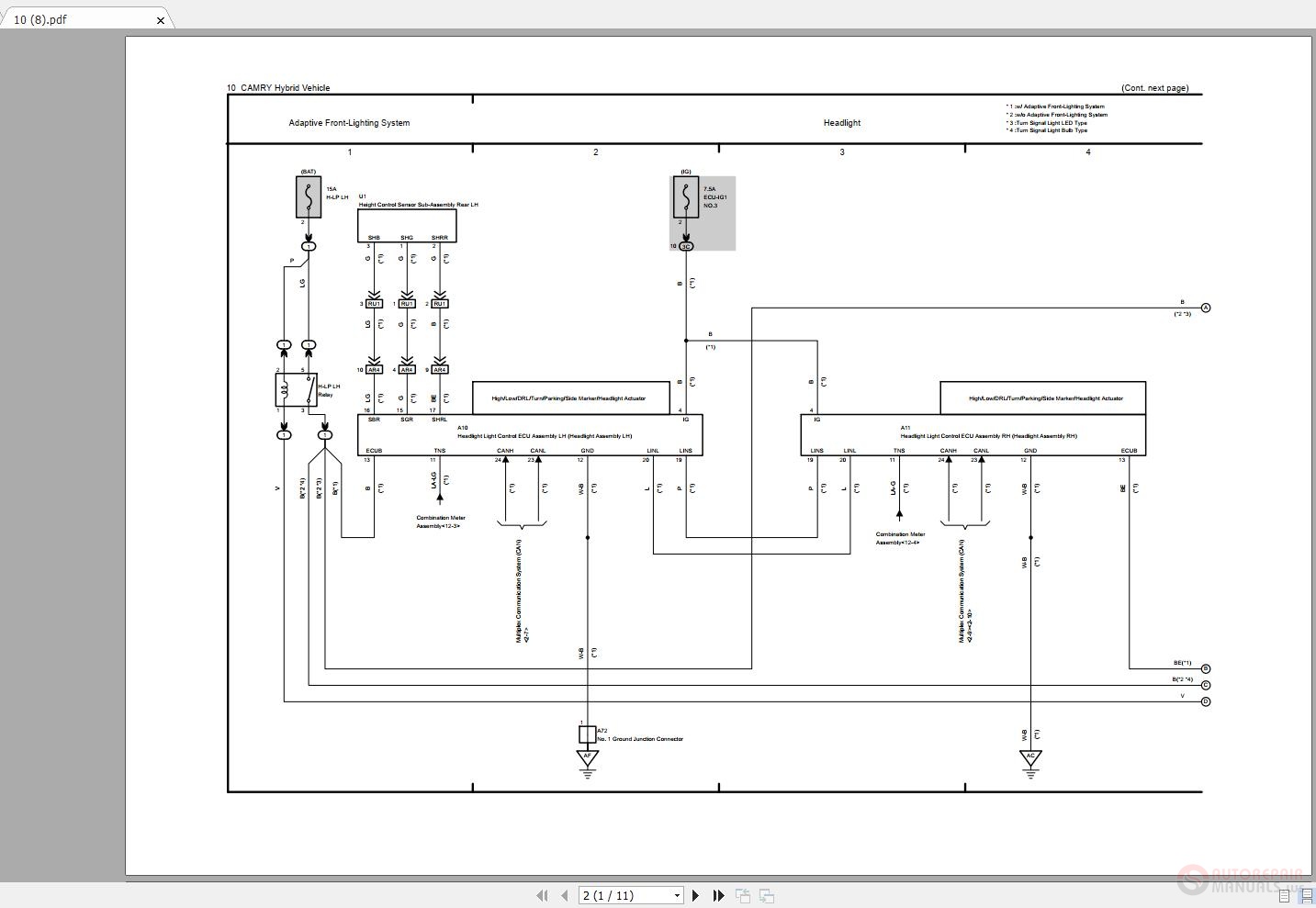
This toyota engine wiring diagram show the left fender wiring along with ecu connector and pin out. It reveals the parts of the circuit as streamlined forms, and the power and also signal links between the devices. The following diagrams may differ slightly depending on vehicle year, or model (california or federal). Electrical schematic & wiring diagrams. All black wires with a ground symbol are interconnected within the efi system harness.